
AMERICAN MANUFACTURING PROJECT · MACHINE DEVELOPMENT
Wallasch CNC Systems
COMPACT MILL DEVELOPMENT
Wallasch Compact CNC Milling Machine
Explore the moving axes, supported workholding and manual tooling in our compact milling-machine development. These views come from the actual CAD assembly and show how its proposed parts relate to the machine.
Why compact CNC cells matter →
Explore the three connected cell systems →
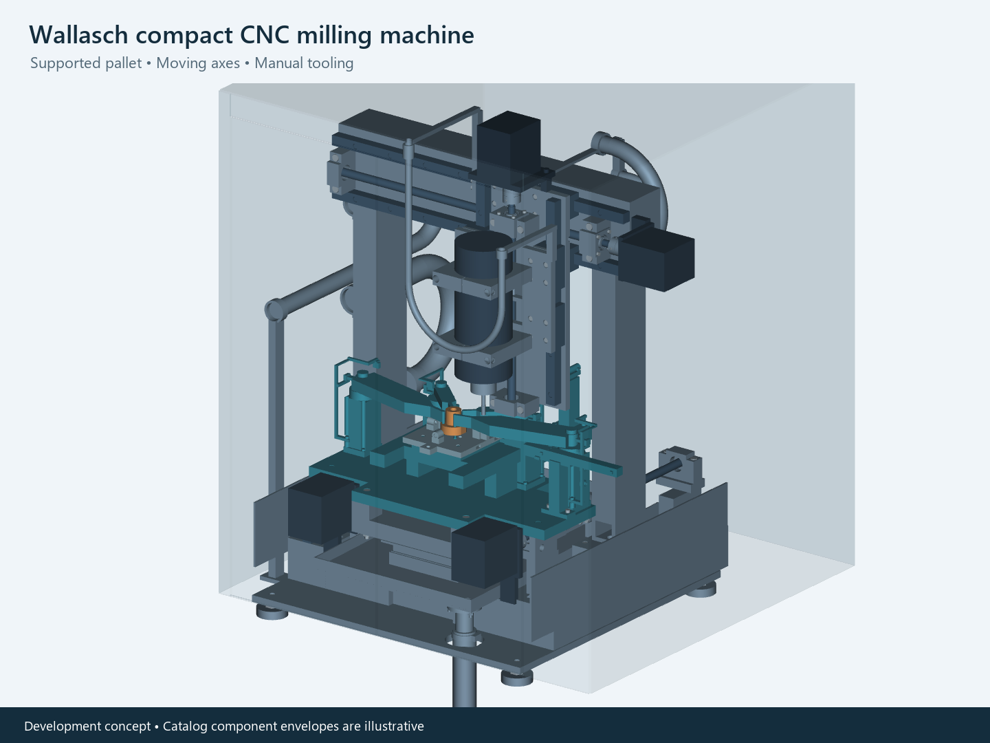
See the proposed machining sequence
The 48-second CAD animation follows a restricted tool path through contour milling, drilling and thread-milling illustrations. The head parks before a clamp changes position; the pallet remains supported. Explicit pauses identify manual tool replacement rather than an automatic tool changer.
Development concept • Illustrative motor envelopes and motion, not validated physical simulation. Material removal and cutting forces are not simulated. Covers and service lines are hidden for clarity; timing does not establish a production cycle or safe operating procedure.
How the pieces work together
Eight component groups explain the machine’s structure and motion, with illustrative motor envelopes. Their grouping does not establish assembly access, cutting performance or production readiness. Open the complete component overview
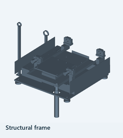
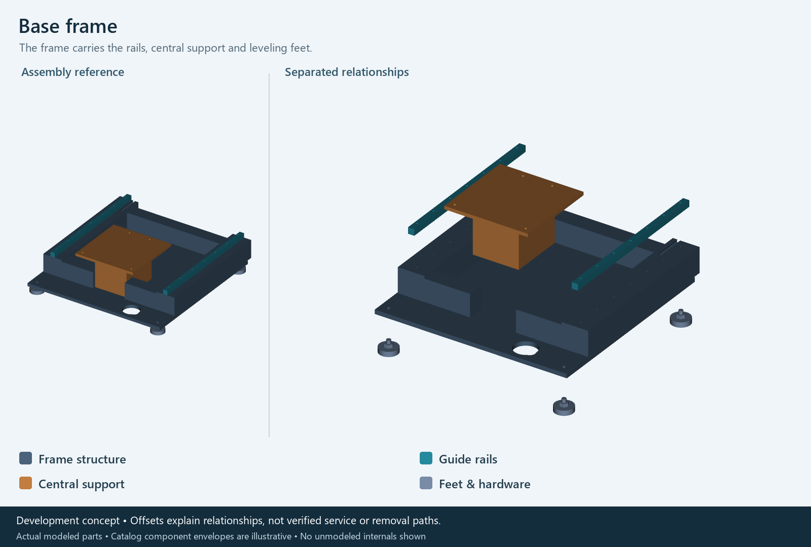
Structural frame
Supports the moving axes and fixed workholding.
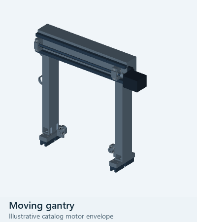
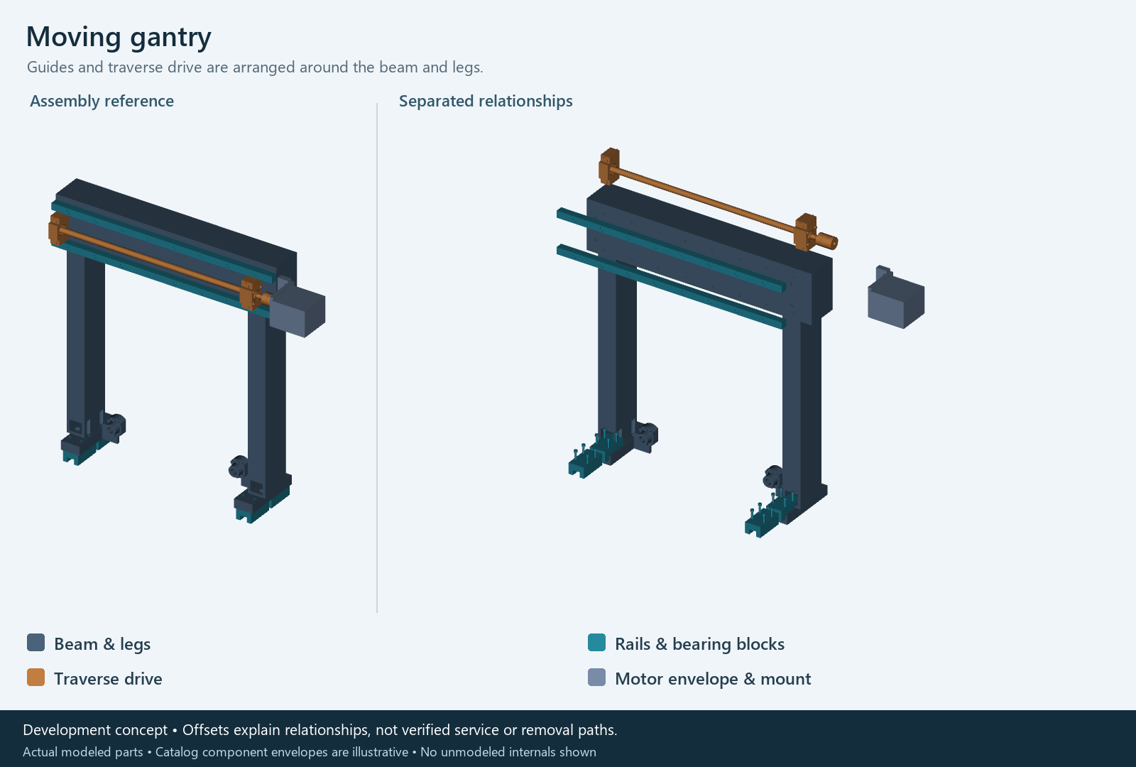
Moving gantry
Carries the cross-axis assembly along the machine’s length. The proposed motor is an illustrative envelope.
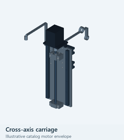
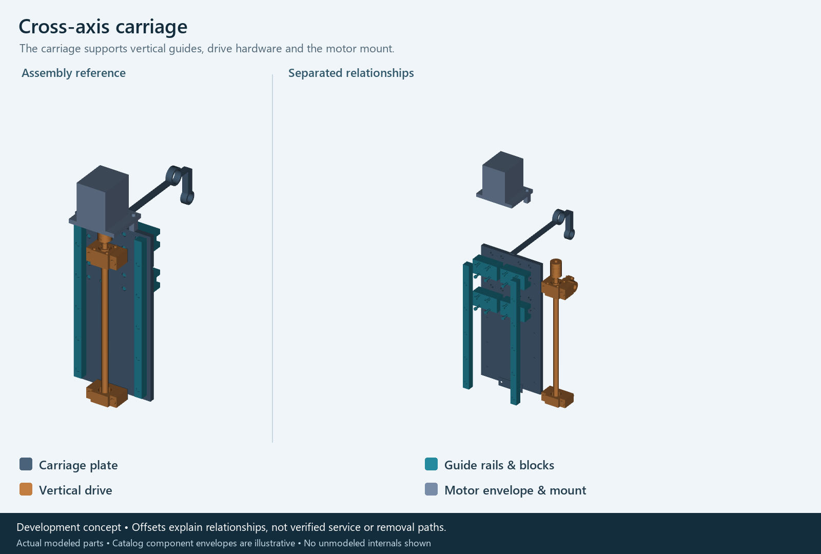
Cross-axis carriage
Moves the vertical head across the gantry. The proposed motor is an illustrative envelope.
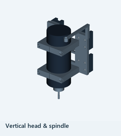
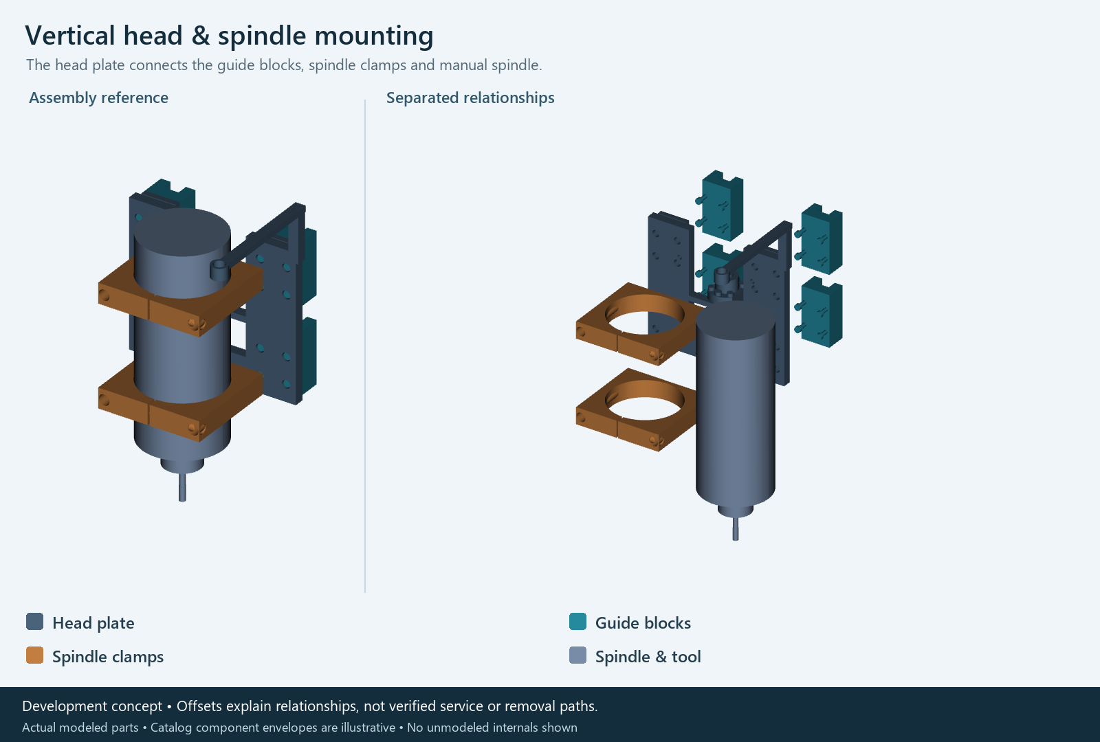
Vertical head and spindle
Positions the tool vertically, with manual tool replacement.
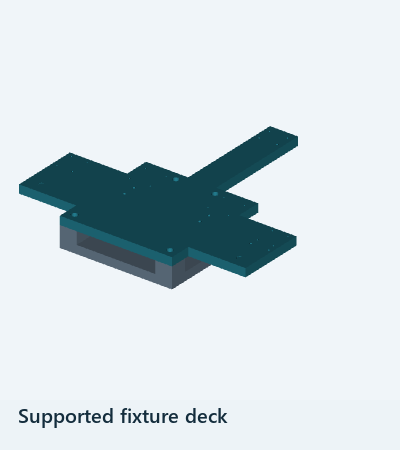
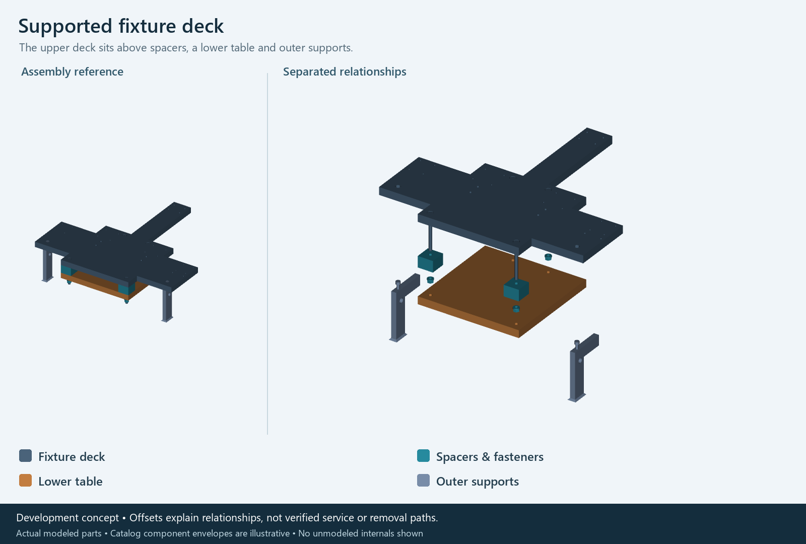
Supported fixture deck
Supports the receiver and workholding above the base.
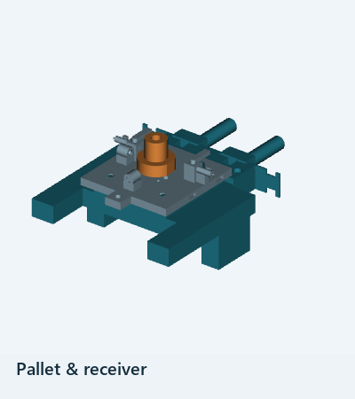
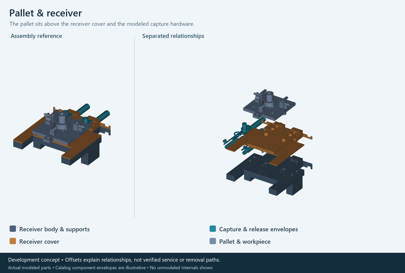
Pallet and receiver
Defines the modeled removable-pallet interface.
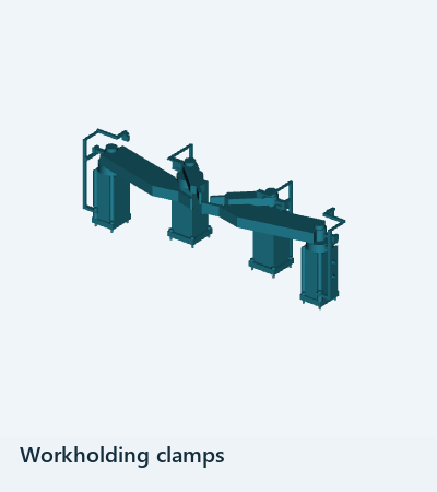
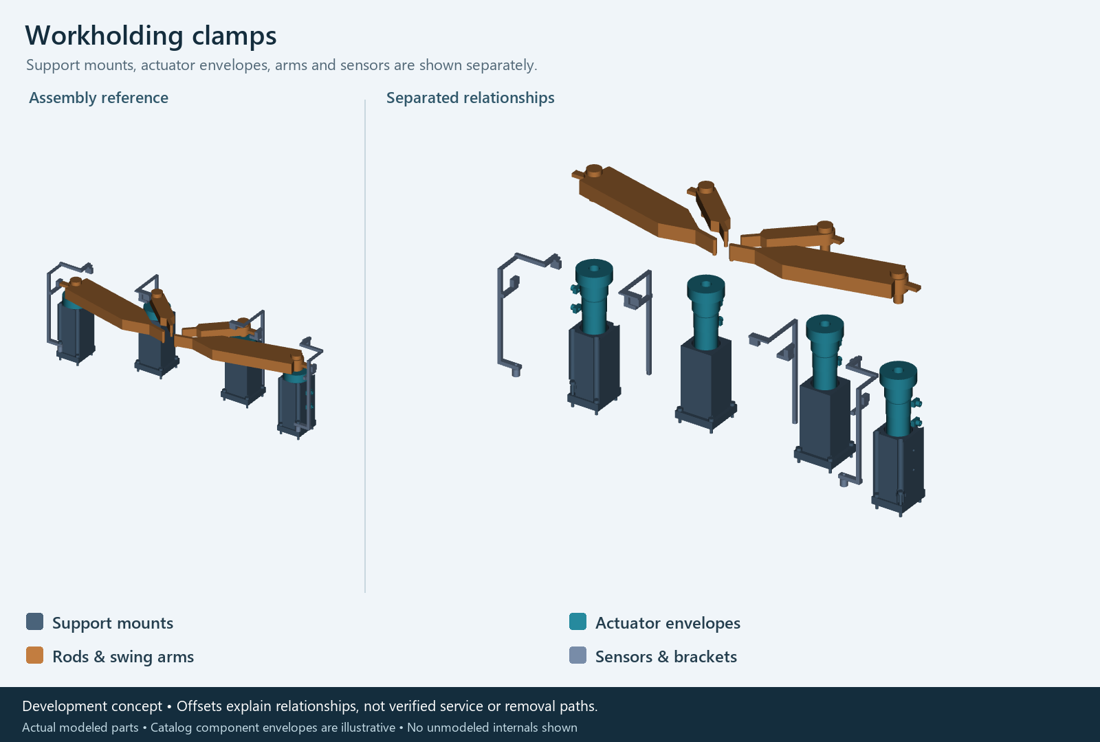
Workholding clamps
One clamp repositions while the head is parked and the remaining clamps stay closed.
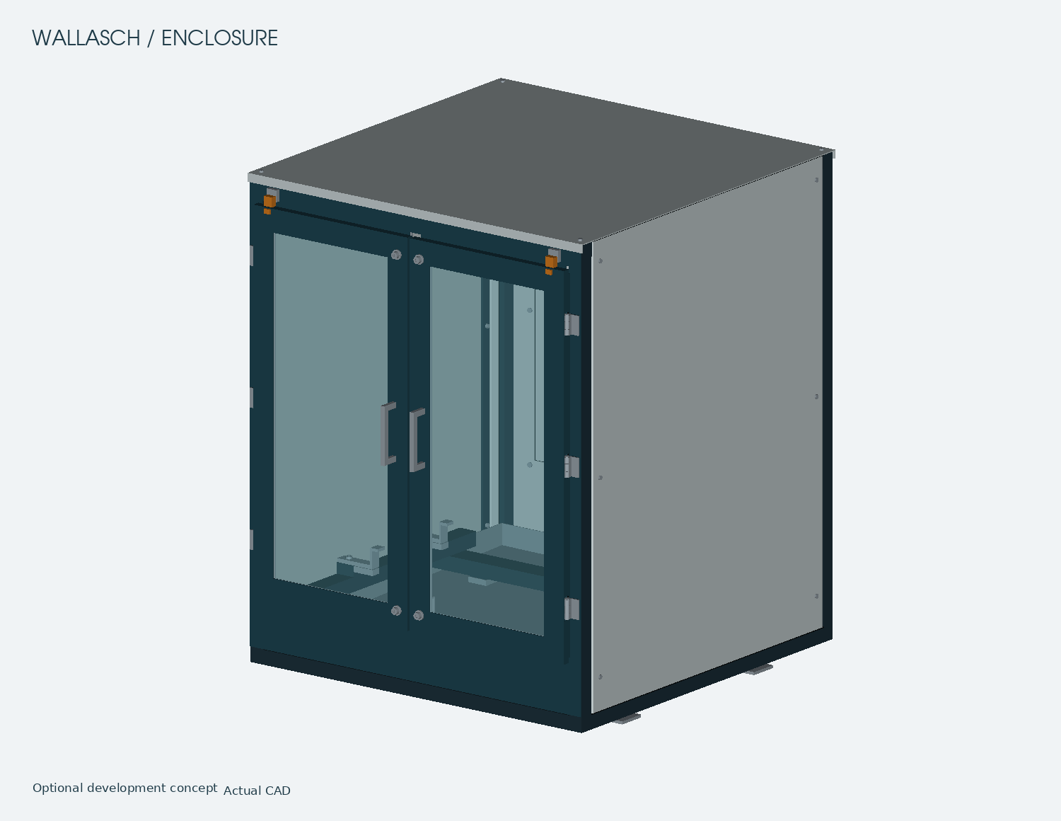
Optional enclosure
A separate enclosure concept with viewing doors, removable panels and internal machine supports.
Component split views
Compare each assembled group with its separated CAD view. The offsets explain component relationships; assembly access, interfaces and removal paths remain unvalidated. Proposed motor and actuator envelopes do not show unmodeled internals.
Structural frame
Moving gantry
Cross-axis carriage
Vertical head and spindle
Supported fixture deck
Pallet and receiver
Workholding clamps
OPTIONAL ENCLOSURE DEVELOPMENT
Enclosure and supporting structure
A separate optional enclosure study for the compact machine, shown closed and separated to explain how the panels, viewing doors, pan and supporting frame relate. It is not shown as an accepted installation in the machining animation.
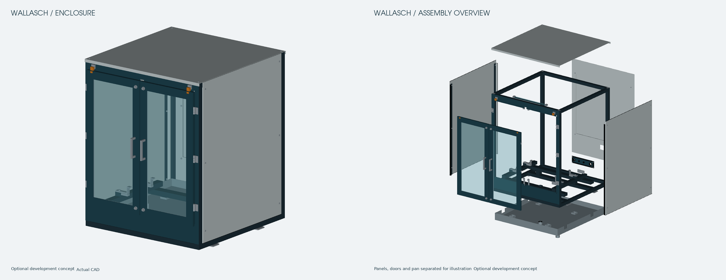
Optional development concept. Structural, sealing and installed-access qualification remain open. Exploded offsets are illustrative rather than verified removal paths.
View doors, panels and internal supports
Optional enclosure concept with the viewing doors closed. Open full-size view
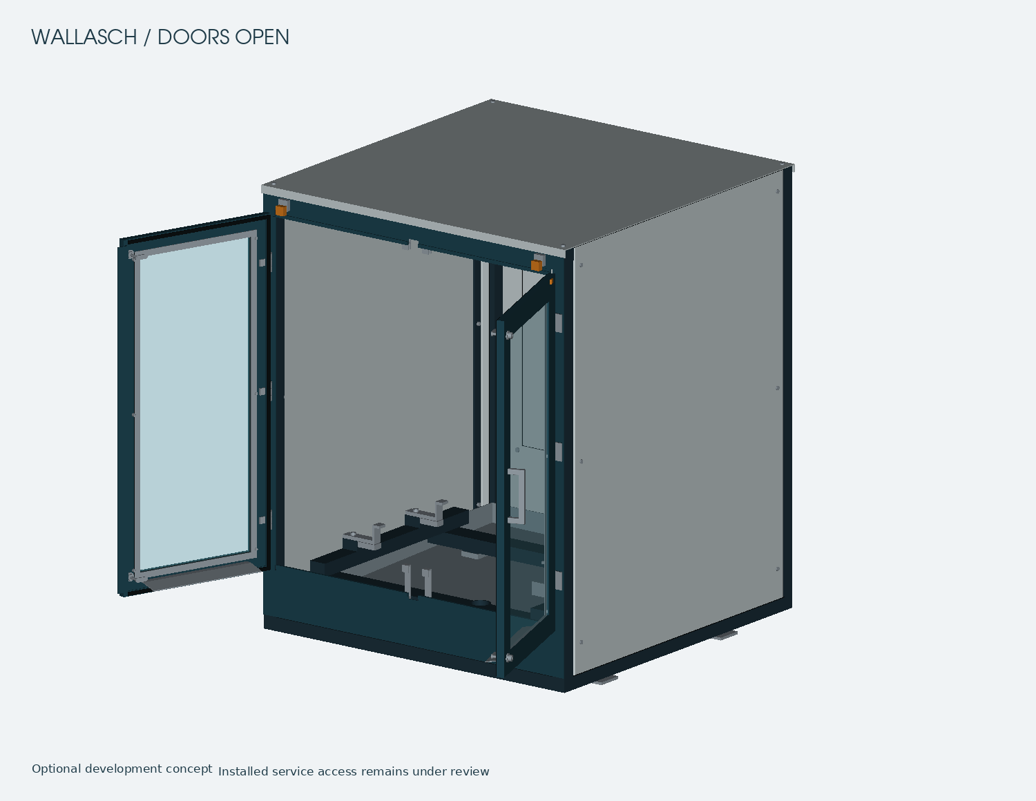
Doors shown open to illustrate the proposed access arrangement. Installed service access remains under review. Open full-size view
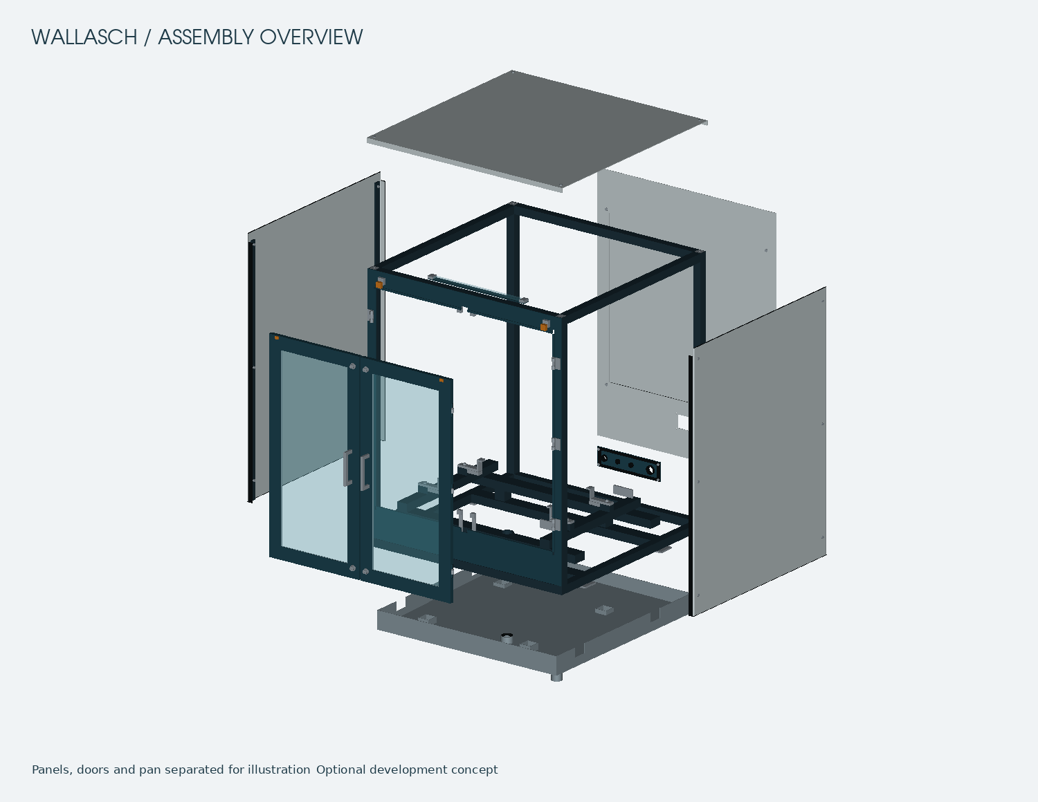
Outer panels, doors and the pan are separated around the supporting frame. Offsets explain assembly relationships, not verified removal paths. Open full-size view
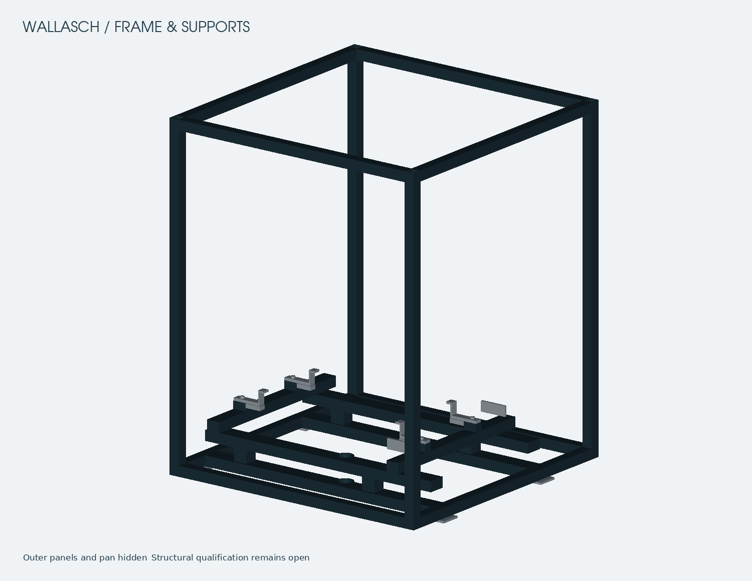
The enclosure frame and internal machine supports, with the outer panels and pan hidden. Structural qualification remains open. Open full-size view
Explore subsystem separation and pallet preparation
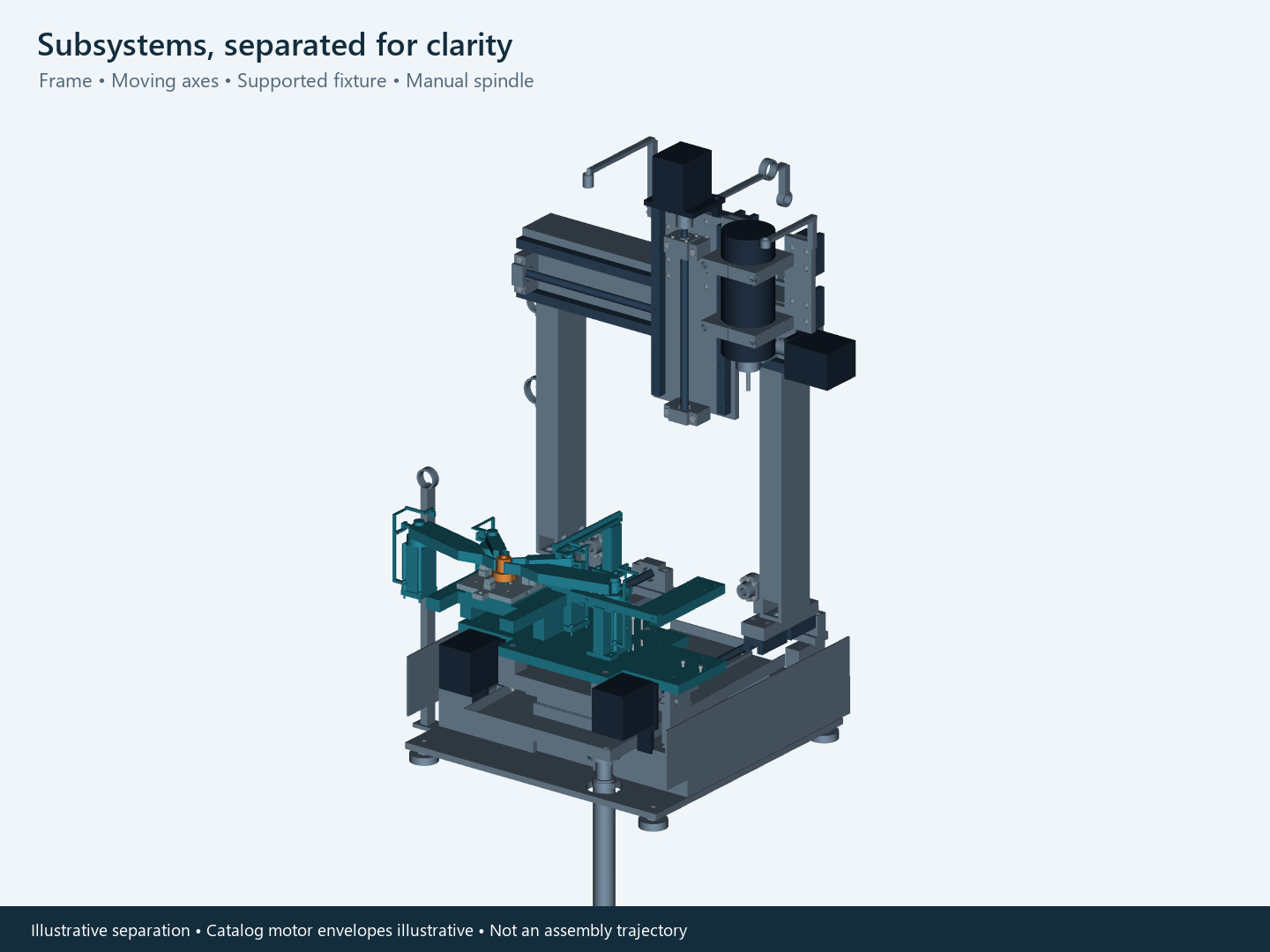
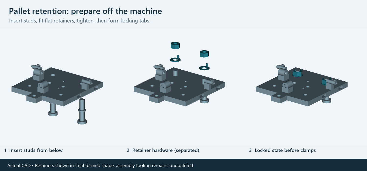
Separate proposed subsystems
The following studies are being developed alongside the base mill. They are separate proposed modules; spindle, carousel and rotary fit with the mill has not been accepted.
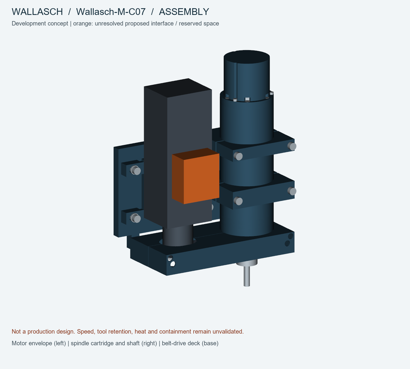
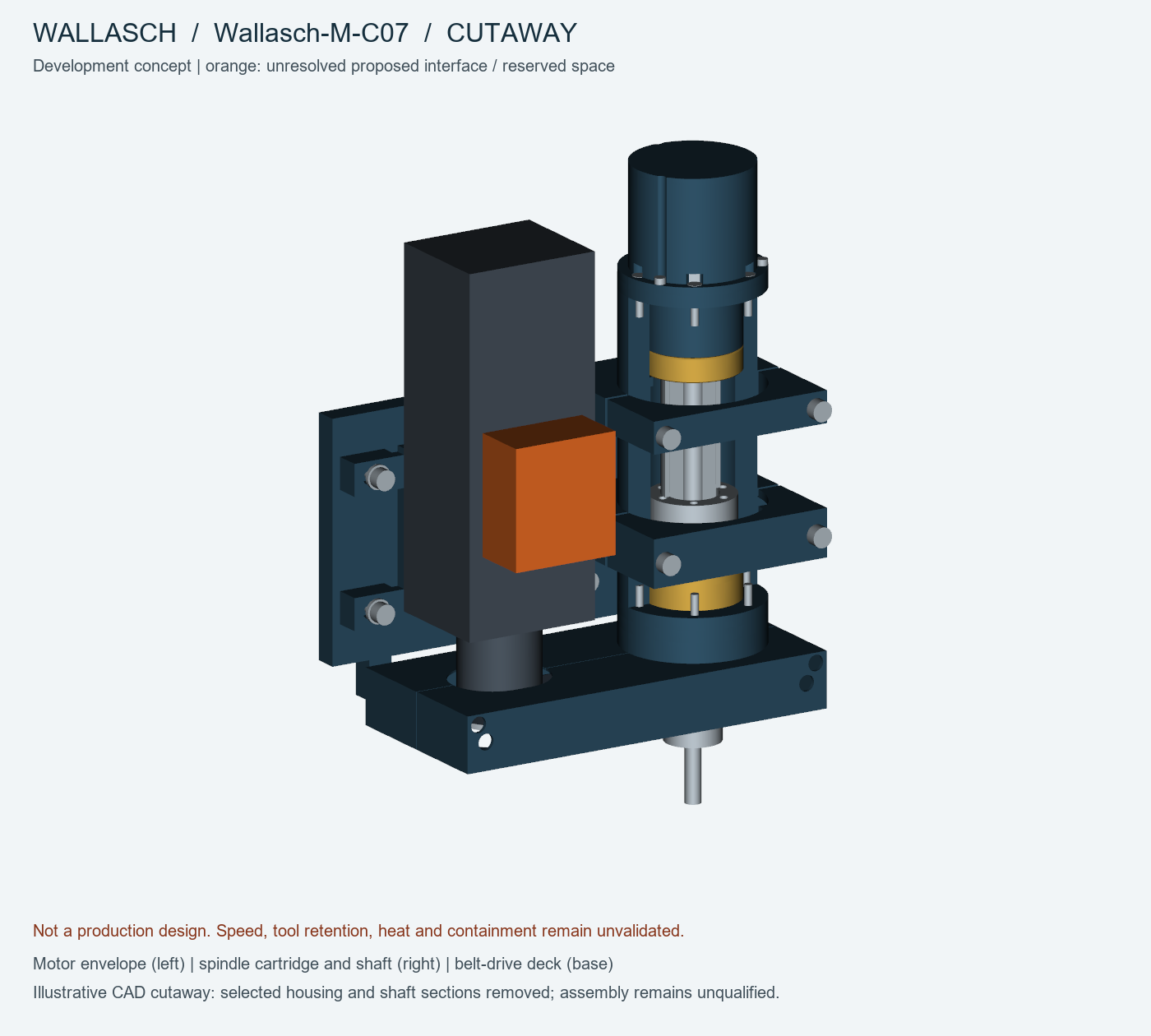
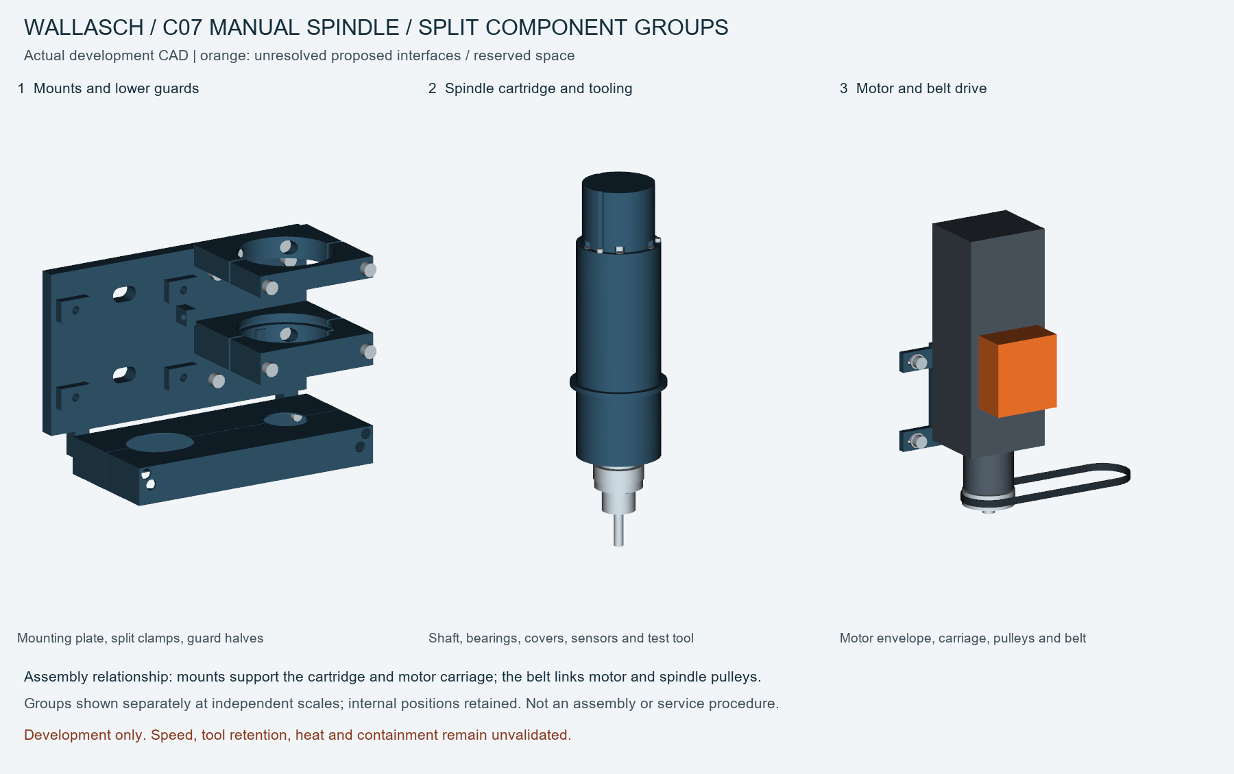
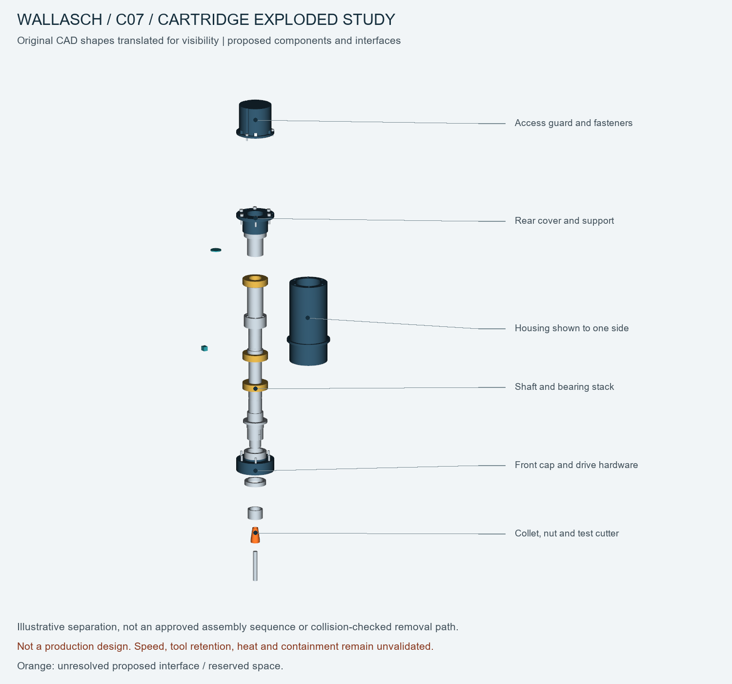
Spindle assembly and internal relationships
The C07 study places a motor envelope alongside a spindle cartridge and shaft, with a belt-drive deck at the base. Orange indicates an unresolved proposed interface or reserved space. Speed, tool retention, heat and containment remain unvalidated.
Split component groups
Manual tool-carousel station and enclosure
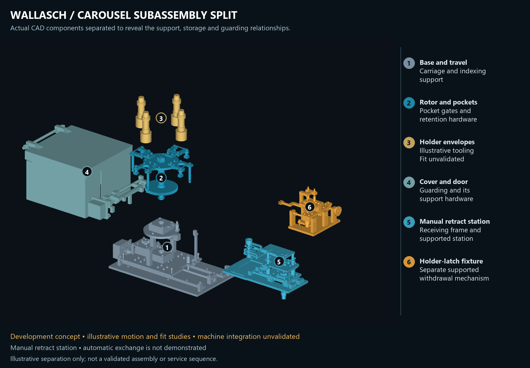
The A9 study explores a supported, manually retractable station with guides and removable captures. The closed view shows the station retracted and held, with the door and hood closed. Fit, actuation, loads and machine integration remain unqualified; automatic exchange is not demonstrated.


Carousel subassemblies


Optional rotary axes: fourth- and fifth-axis development remains a separate proposed capability. No accepted rotary fit or simultaneous-axis machining capability is claimed for this mill.
Development concept, not for sale. Cutting performance, accuracy, loads, control behavior and safe operation remain unvalidated. The design is not released for manufacture or powered operation.