
WPM-P010 · MANUFACTURING-DEVELOPMENT STUDY
Spring-floating edge scraper
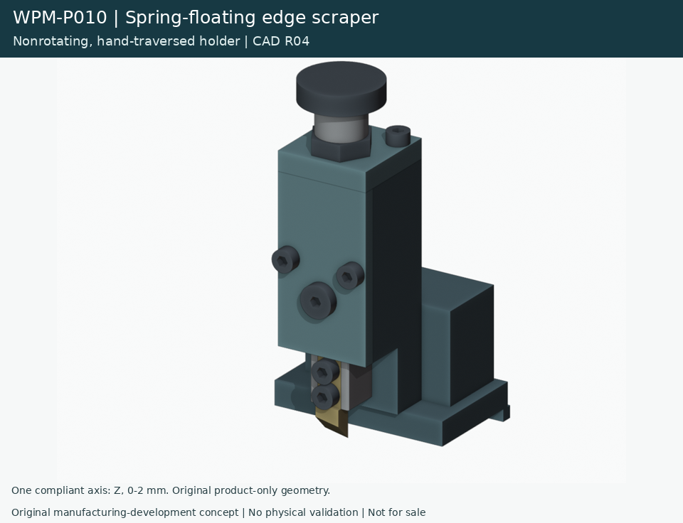
A hand-traversed holder explores a single constrained Z-compliance axis, illustrative adjustable preload and a retained replaceable insert.
The motion is prescribed no-cut contact-following over assumed variation. Cutting, spring behavior, force, fits, safety and production performance are unvalidated. The holder does not rotate and has no independently compliant side-to-side axis.
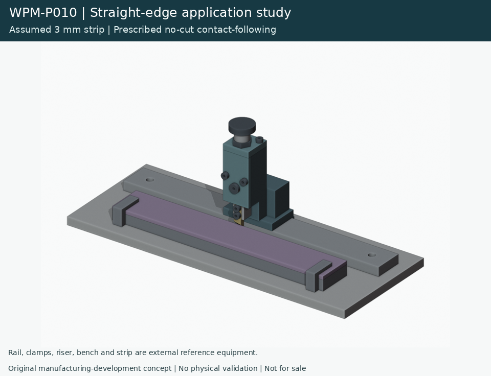
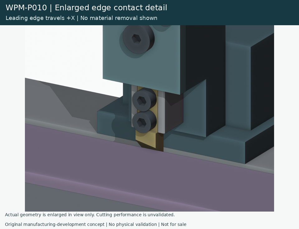
Prescribed contact-following
The 14-second illustration follows an assumed edge-height variation with no material removal. Motion is prescribed; it does not simulate cutting, contact force or physical spring response.
Mechanism section
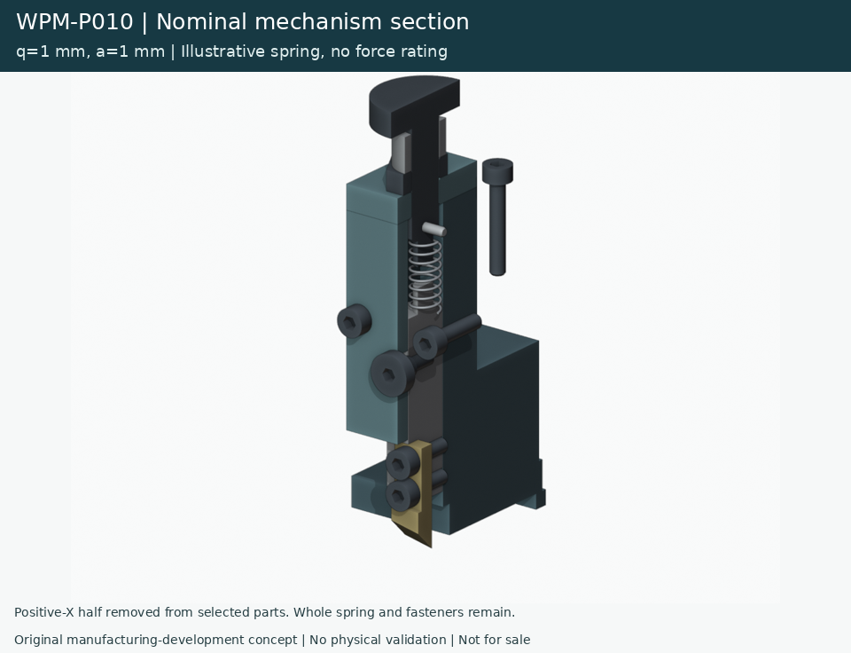
The 17-second section illustration shows the single-axis guided relationship. Sectioning and motion explain geometry without validating spring stress, forces or friction.
Components and assembly
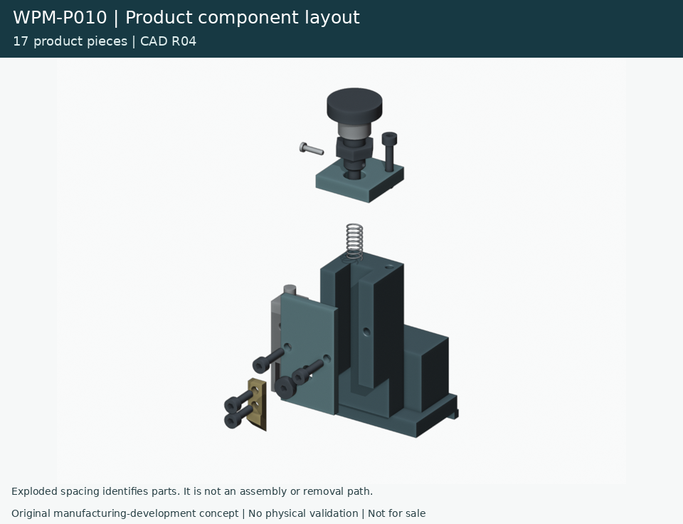
A 34-second staged assembly illustration. Thread rotation, tools, hands and temporary supports are simplified or omitted. It is not a manufacturing instruction.
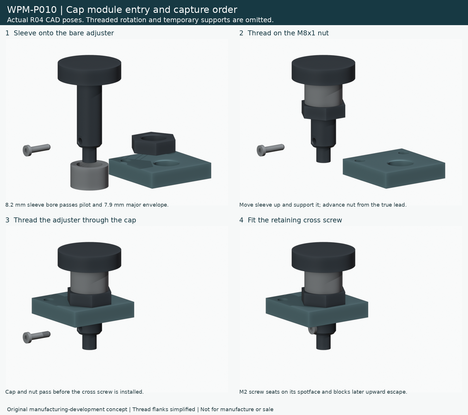
Disassembly and insert service
A 34-second nominal disassembly illustration. Actual access, support, fits and handling require physical validation.
A 14-second replaceable-insert service illustration. This shows component relationships; safe isolation, access and replacement performance are unvalidated.
Manufacturing development ahead
Materials, fits, wear, retention, physical handling, safeguarding and application-specific testing remain open. These nominal CAD views support manufacturability discussions; they are not released build or service instructions.
WPM is a manufacturability and onshoring company, not an engineering firm. This original hypothetical study does not establish professional engineering approval, legal clearance or production readiness.
Study scope
17 nominal product solids. External reference rail, workholding and strip excluded. Cutting, spring, force, fit and safe use remain unvalidated. Thread rotation and supports are simplified.
V30 identifies the review checkpoint; the actual CAD revision is R04. This is an original hypothetical study, not customer work.