
WPM-P005 · MANUFACTURING-DEVELOPMENT STUDY
Manual rotary positioner
A hand-driven worm adjustment, separate friction brake and index pin explore three distinct functions in a compact bench fixture.
Holding strength, accuracy, repeatability, capacity and manufacturing performance remain unvalidated. The worm drive is not assumed to be self-locking. No economic or production benefit is established.
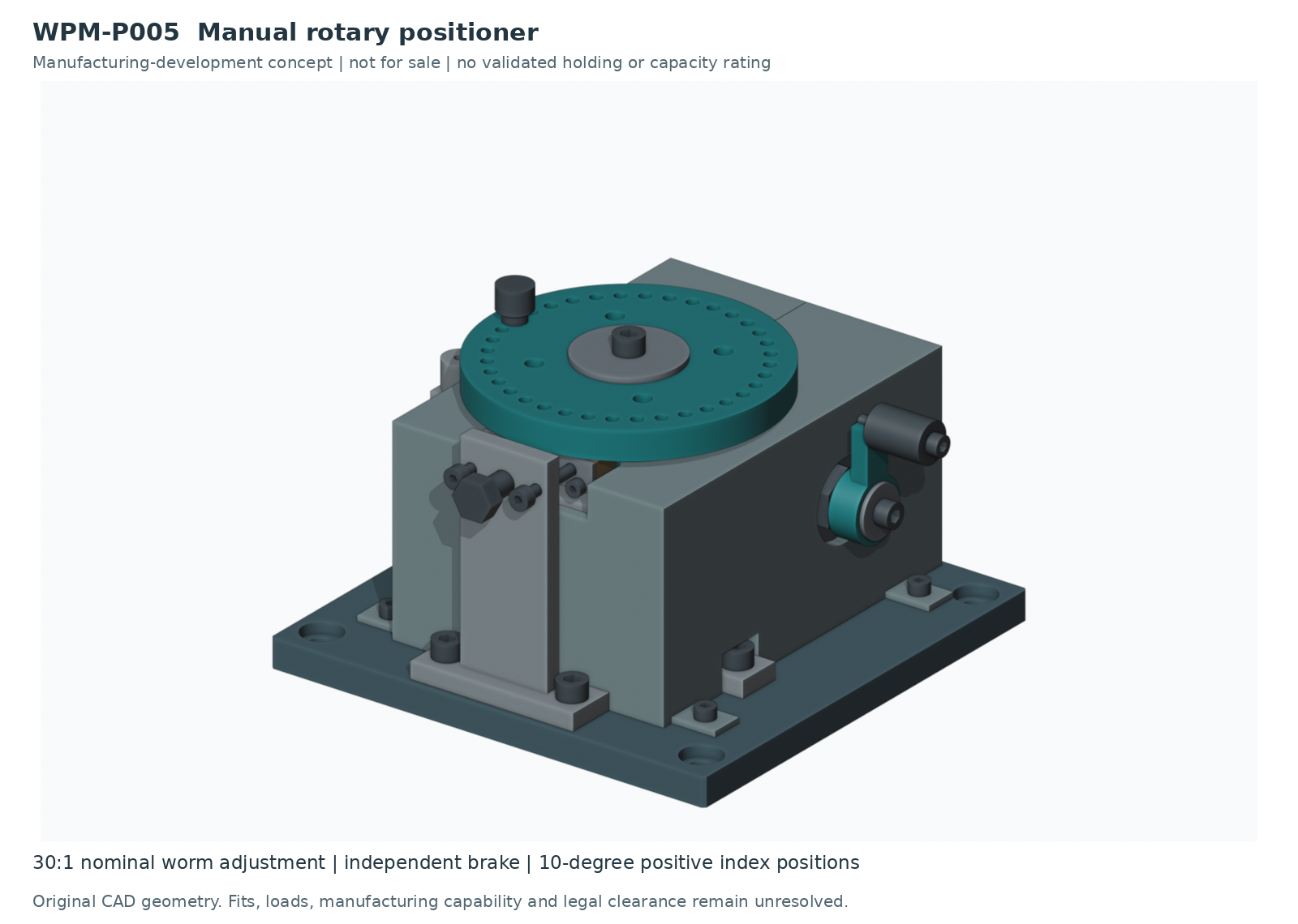
Adjustment and positioning
The 28-second illustration shows prescribed adjustment and positioning relationships. Hands, thread action, friction, loads and deformation are simplified or omitted. No tested holding or precision is demonstrated.
Inside the gear train
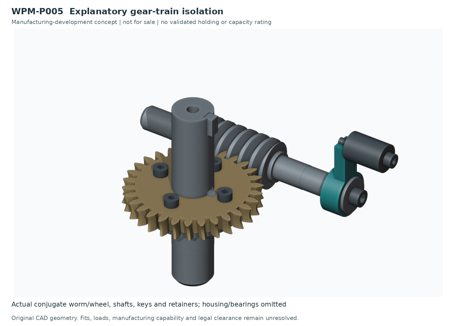
This eight-second isolated gear-motion study omits housing and bearings to expose the worm and wheel. It is an explanatory CAD view, not an unsupported operating assembly.
Assembly and disassembly
A 75-second staged assembly illustration. Pause or use fullscreen to inspect the sequence. Threads, hands, tools and temporary supports are simplified; physical assembly feasibility and safe handling remain open.
A 75-second nominal disassembly illustration. It explains component relationships without validating a removal path, service procedure or load isolation.
An 11-second exploded arrangement highlights component groups. Spacing is explanatory and does not establish a physical assembly order.
Output support and brake sections
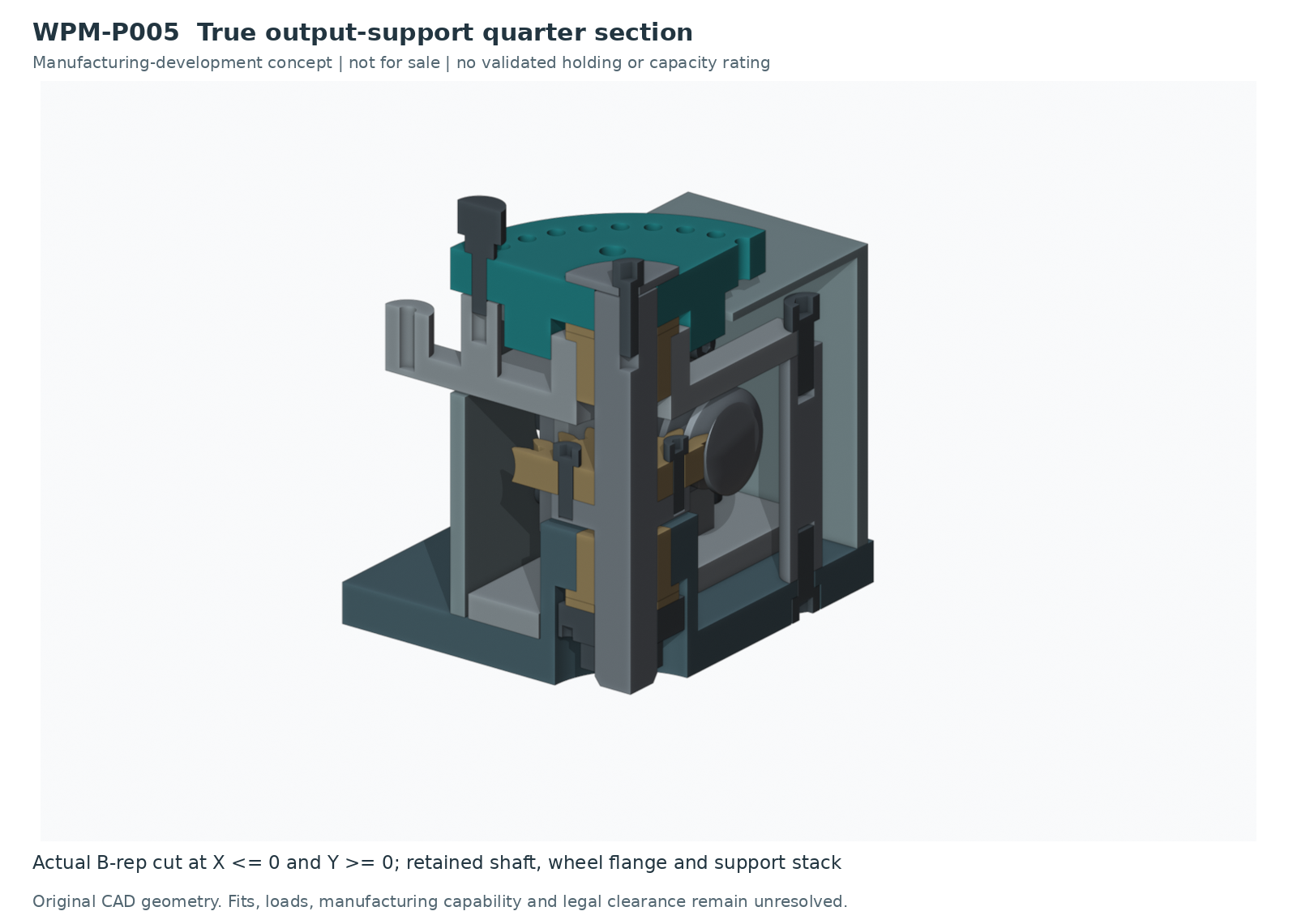
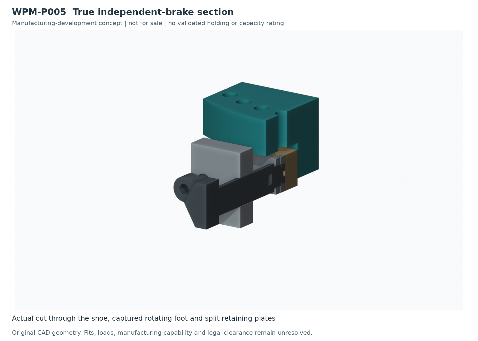
Subassembly details
Approximately 12 seconds: nominal bearing-support component relationships. Clearances and assembly forces are not validated.
Approximately 16 seconds: the separate brake components assemble in a schematic CAD sequence. This does not establish a brake torque or safety function.
Seven seconds: the hand-crank subassembly illustrates retained component relationships. Thread action and tool use are simplified.
Brake service illustration
Approximately 16 seconds: isolated brake-service relationships. Real load isolation, hand access, replacement fits and a safe service procedure require development.
Manufacturing development ahead
Materials, fits, wear, retention, physical handling, safeguarding and application-specific testing remain open. These nominal CAD views support manufacturability discussions; they are not released build or service instructions.
WPM is a manufacturability and onshoring company, not an engineering firm. This original hypothetical study does not establish professional engineering approval, legal clearance or production readiness.
Study scope
91 nominal product solids. Reference fixture excluded. Fits, loads, holding performance and manufacturing details are unvalidated. Simplified thread and purchased-part geometry is for concept review only.
V30 identifies the review checkpoint; the actual CAD revision is v21. This is an original hypothetical study, not customer work.